ABViewer How-to Guide
ABViewer supports:
- 2D CAD formats: AutoCAD DWG (2.5 up to 2023 inclusive), DXF (ASCII DXF/BINARY all versions), DWT, DWF.
- Vector formats: PDF, WMF, EMF, SVG, PLT, HPGL, EPS, CGM.
- 3D formats: IGES, STEP, SLDPRT, SLDASM, X_T, X_B, STL, OBJ, SAT, 3DS.
- Raster formats: JPEG, PNG, TIF, BMP.
 To get a full list of supported formats please visit our help page.
1. Run ABViewer.
2. Go to File and select the PDF to DWG command.
3. In the opened Converting window, select a PDF file you want to convert and change the output file path, if required. You can also select the output file format: DWG 2000/2004/2010, DXF 2000/2004/2007.

4. Click OK. The conversion process may take some time depending on the size of the original PDF file and the number of pages.
 To know more about the PDF to CAD conversion please visit our help page.
ABViewer has easy-to-use measuring tools that enable to get:
- distance between two points;
- distance between two circle centers;
- distance between two parallel edges;
- height between two parallel surfaces;
- length of a linear or curvilinear edge;
- area;
- volume;
- overall dimensions.
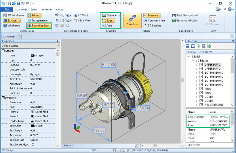
When you finish measuring you can print your 3D model, save it as BMP or save all the measurements you made in a separate file and load them when necessary.
 To know more about the 3D measuring tools please visit our help page.
1. Open your 3D model.
2. Select the 3D Section command.
3. In the opened window, click ![]() to add a new section plane.
to add a new section plane.
4. Adjust the section plane position by changing the parameter values in the 3D Section window or moving the 3D gizmo handles.
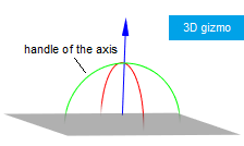
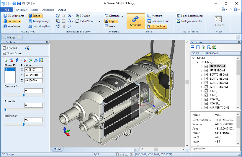
 To know more about the 3D section tool please visit our help page.
1. Open your DWG or DXF file. If you need to edit it, use the tools on the Editor tab.
2. Go to the Output tab and select the CAD to G-code command. The G-code mode of ABViewer will be activated.
3. Configure all the settings you need.
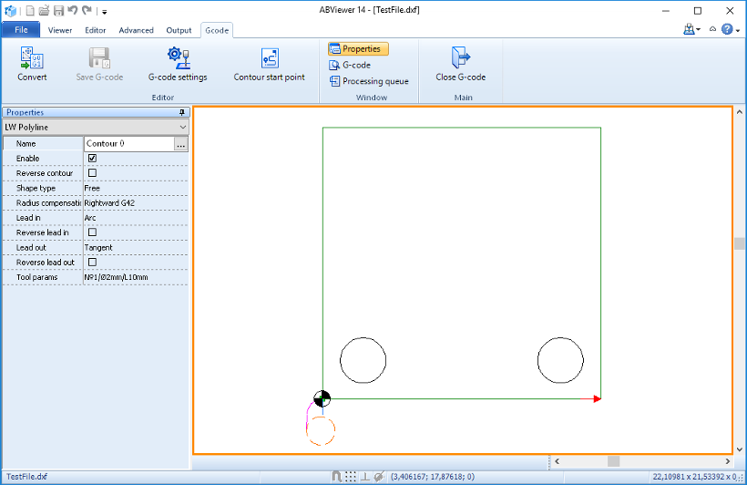
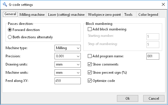
By default, ABViewer generates G-code for a milling machine. You can change a machine type in the G-code settings window on the General tab.
4. Click Convert. And then click Save G-code.
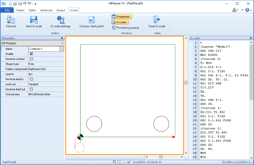
 To know more about G-code generation please visit our help page.
1. Open your 3D file.
2. Go to File and select the Save as command.
3. In the opened window, specify the output file name and file format (AutoCAD DWG or DXF).
 It also possible to convert 3D files to STL, OBJ, PDF or raster image. To get a full list of supported export formats please visit our help page.
1. Go to the Advanced tab and select the Compare files command.
2. In the opened window, select your two DWG/DXF files to compare.
3. Configure the settings you need. ABViewer has two comparison modes. The first one enables to compare the drawing content. The second one enables to compare only the graphics.
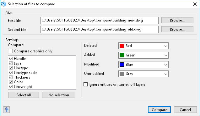
4. Click Compare. As a result, all the modified, deleted and added entities will be highlighted.
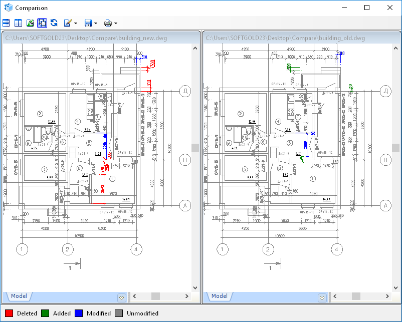
 To know more about the comparing tool please visit our help page.

